|
Directions: It is the practice in electrical engineering to represent the imaginary unit, i, by the letter "j", to avoid confusion with the symbol for electric current which is I. This page will, however, continue to use the letter i for the imaginary unit. Be sure to read the passage following question #5 before attempting the remaining questions.
1. |
The relationship between voltage, E (volts), current, I (amps), and impedance, Z (ohms), in an alternating circuit, is given by the formula E = I • Z. If the circuit has a current I = 3 + 2i and an impedance Z = 2 - i, what is the voltage of this circuit?
|
|
|
|
2. |
Impedance measures the opposition of an electrical circuit to the flow of electricity. The total impedance in a parallel circuit is given by the formula  . What is the total impedance of a circuit, ZT , if Z1 = 1 + 2 i
and Z2 = 1 - 2 i ?
|
|
|
Choose:
|
|
3. |
The impedance in one component of a series circuit is 2 + 6i ohms, and the impedance in another component of the circuit is 5 - 3i ohms. The "impedance" for a series circuit is the sum of the impedances for its individual components. Find the impedance in this circuit. |
|
|
|
4. |
The current in a circuit is 4 + 3i amps and the impedance is 6 - 2i ohms. By using the formula E = I • Z described in question 1, find the voltage.
|
|
|
|
5. |
The voltage in a circuit is 35 + 12i volts and the impedance is 4 + 5i ohms. By using the formula E = I • Z described in question 1, find the current.
|
|
|
|
AC circuit components such as resistors, inductors and capacitors all oppose the flow of current. The opposition to current is referred to as resistance for resistors and reactance for inductors and capacitors. The total opposition to current flow in a circuit is called impedance, Z, measured in ohms,  . (Note in the table below that impedance referred to as resistance is represented with a Real Number while impedance referred to as reactance is represented with an Imaginary Number. Impedance from Inductors is positive, and from Capacitors is negative.) . (Note in the table below that impedance referred to as resistance is represented with a Real Number while impedance referred to as reactance is represented with an Imaginary Number. Impedance from Inductors is positive, and from Capacitors is negative.)
Circuit Component |
Symbol |
Impedance (Z) |
Resistor |
 (5  ) ) |
Z = 5 |
Inductor |
 (6 (6  ) ) |
Z = 6i |
Capacitor |
 (7 (7  ) ) |
Z = -7i |

In a series circuit, the impedance is the sum of the impedances for the individual components.
In a parallel circuit, there is more than one pathway through which the current can flow. To find the total impedance, ZT , first calculate the impedances Z1 and Z2 of the pathways separately, by treating each pathway as a series circuit. Then apply the formula  . .
6. |
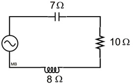
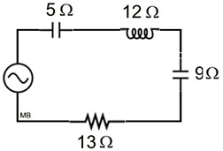
A series circuit is shown at the right, where electricity flows in only one direction. Find the impedance, Z, of this circuit, in ohms.
|
|
|
|
7. |
A series circuit is shown at the right. Find the impedance, Z, of the circuit. |
|
|
|
8. |
A series circuit is shown at the right. Find the impedance, Z, of the circuit. |
|
|
|
9. |
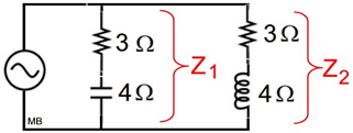
A parallel circuit is shown at the right. Find the impedance, Z of the circuit.
|
|
|
|
10. |
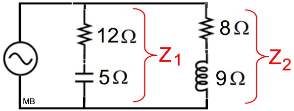
A parallel circuit is shown at the right. Find the impedance, Z, of the circuit.
|
|
|
|

NOTE: The re-posting of materials (in part or whole) from this site to the Internet
is copyright violation
and is not considered "fair use" for educators. Please read the "Terms of Use". |
|

 . What is the total impedance of a circuit, ZT , if Z1 = 1 + 2i